 |
Главная Случайная страница Контакты | Мы поможем в написании вашей работы! | |
Figure 2. Communication diagram with nested decimal numbering
|
|
26. Composite structures: definition, description, example.
Def: Composite structure diagram visualizes the internal structure of a class or collaboration. It is a kind of component diagram mainly used in modeling a
system at micro point-of-view.
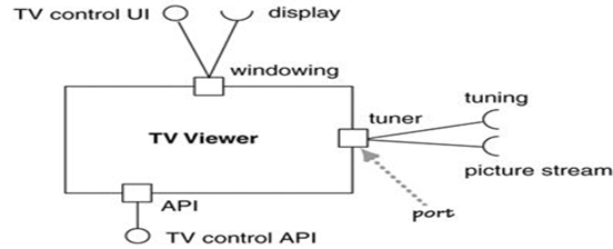
Descr: We can use the composite structure diagram to show the internal details of a classifier and to describe the objects and roles that work together to perform the behavior of the containing classifier.
We can add ports to the external structure. Ports allow you to group the required and
provided interfaces into logical interactions that a component has with the outside world
Parts
In composite structure diagrams, a part is a diagram element that represents a set of one or more instances that a containing structured classifier owns. A part describes the role of an instance in a classifier. You can create parts in the structure compartment of a classifier, and in several UML diagrams such as composite structure, class, object, component, deployment, and package diagrams.
Ports
In composite structure diagrams, a port defines the interaction point between a classifier instance and its environment or between the behavior of the classifier and its internal parts.
Example:
27. Main elements of component diagram: definitions, description, examples.
Def: Component diagram shows the physical aspect of an object-oriented software system. It illustrates the architectures of the software components and
dependencies between them.
Des:
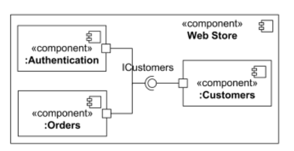
Components are connected through implemented and required interfaces.
The important point is that components represent pieces that are independently purchasable and upgradeable. As a result, dividing a system into components is as much a marketing decision as it is a technical decision, for which is an excellent guide.
Use component diagrams when you are dividing your system into components and want to show their interrelationships through interfaces or the breakdown of components into a lower-level structure.
Example:
28. Collaborations: definition, description, example.
Def: UML Collaboration diagrams (interaction diagrams) illustrate the relationship and interaction between software objects. The collaboration diagram illustrates messages being sent between classes and objects (instances). A diagram is created for each system operation that relates to the current development cycle (iteration). When creating collaboration diagrams, patterns are used to justify relationships. Patterns are best principles for assigning responsibilities to objects and are described further in the section on patterns. There are two main types of patterns used for assigning responsibilities which are evaluative patterns and driving patterns.
In a collaboration, the naming scheme is participant-name/ role-name: class-name. As usual, all these elements are optional.
Descr: Collaborations do provide a way to group chunks of interaction behavior when roles are played by different classes.
Example: 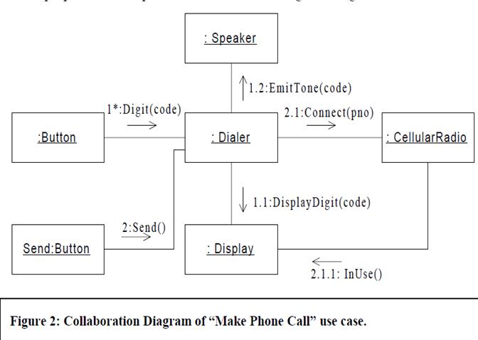
29. Main elements of interaction overview diagram: definitions, description, examples.
Def: Interaction overview diagram is the variant of activity diagram. Interaction overview diagrams overview control flow. The main element, frame showsany type of interaction diagram.
Des: Interaction overview diagrams are very similar to activity diagrams. While activity diagrams shows a sequence of processes Interaction overview diagrams shows a sequence of interaction diagrams.
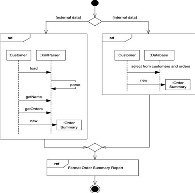
Interaction overview diagrams are a grafting together of activity diagrams and sequence diagrams. We can think of interaction overview diagrams either as activity diagrams in which the activities are replaced by little sequence diagrams, or as a sequence diagram broken up with activity diagram notation used to show control flow. Either way, they make a bit of an odd mixture.
Example. In this diagram, we want to produce and format an order summary report. If the customer is external, we get the information from XML; if internal, we get it from a database. Small sequence diagrams show the two alternatives. Once we get the data, we format the report; in this case, we don't show the sequence diagram but simply reference it with a reference interaction frame.
30. Main elements of timing diagram: definitions, description, examples.
Def: Timing diagram shows time, event, space and signal for real-time and distributed system
Descr: Timing diagrams are useful for showing timing constraints between state changes on different objects. The diagrams are particularly familiar to hardware engineers.
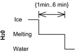
Duration Constraint: Is an interval constraint that refers to a duration interval.
Time constraint is shown as graphical association between a time interval and the construct that it constrains. Typically this graphical association is a small line, between an occurrence specification and time interval.
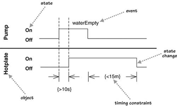
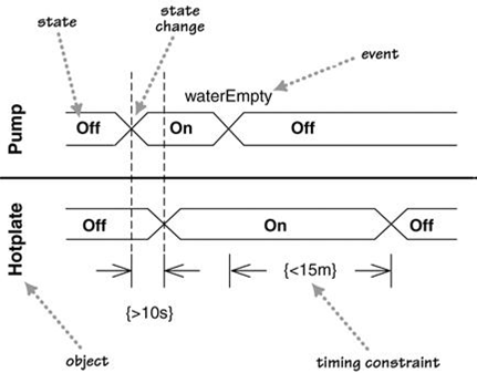
Figures 1 and 2 are alternative ways of showing these timing constraints. Both diagrams show the same basic information. The main difference is that Figure 1 shows the state changes by moving from one horizontal line to another, while Figure 2 retains the same horizontal position but shows state changes with a cross. The style of Figure 1 works better when there are just a few states, as in this case, and Figure 2 is better when there are many states to deal with.
Example:
UML: Exam questions
1. What is the UML?
2. What are ways of using the UML?
3. Describe UML diagrams.
4. How to fit the UML into development process?
5. Notes and comments, constraint rules, keywords on UML diagrams: definitions, description, examples.
6. Main elements of class diagram: definitions, description, examples.
7. Attributes and operations on class diagram: definitions, description, examples.
8. Relationships between classes: definitions, description, examples.
9. Interfaces and abstract classes on class diagram: definitions, description, examples.
10. Main elements of sequence diagram: definitions, description, examples.
11. Creating and deleting participants, synchronous and asynchronous calls on sequence diagram: definitions, description, examples.
12. Loops and conditionals on sequence diagram: definitions, description, examples.
13. Main elements of object diagram: definitions, description, examples.
14. Main elements of package diagram: definitions, description, examples.
15. How to show aspects on package diagram: definition, description, example.
16. Main elements of deployment diagram: definitions, description, examples.
17. Main elements of use case diagram: definitions, description, examples.
18. Levels of use cases on use case diagram: definitions, description, examples.
19. Relationships between use cases: definitions, description, examples.
20. Main elements of state machine diagram: definitions, description, examples.
21. Internal activities, activity states, superstates, concurrent states: definitions, description, examples.
22. Main elements of activity diagram: definitions, description, examples.
23. Decomposing an action on activity diagram: definition, description, example.
24. Partitions, expansion regions, flow final, join specifications: definitions, description, examples.
25. Main elements of communication diagram: definitions, description, examples.
26. Composite structures: definition, description, example.
27. Main elements of component diagram: definitions, description, examples.
28. Collaborations: definition, description, example.
29. Main elements of interaction overview diagram: definitions, description, examples.
30. Main elements of timing diagram: definitions, description, examples.
Practice:
1. An example of class diagram for Visual Studio IDE.
2. An example of sequence diagram for Visual Studio IDE.
3. An example of object diagram for Visual Studio IDE.
4. An example of package diagram for Visual Studio IDE.
5. An example of deployment diagram for Visual Studio IDE.
6. An example of use case diagram for Visual Studio IDE.
7. An example of state machine diagram for Visual Studio IDE.
8. An example of activity diagram for Visual Studio IDE.
9. An example of communication diagram for Visual Studio IDE.
10. An example of component diagram for Visual Studio IDE.
11. An example of class diagram for WinRar archiver
12. An example of sequence diagram for WinRar archiver
13. An example of object diagram for WinRar archiver
14. An example of package diagram for WinRar archiver
15. An example of deployment diagram for WinRar archiver
16. An example of use case diagram for WinRar archiver
17. An example of state machine diagram for WinRar archiver
18. An example of activity diagram for WinRar archiver
19. An example of communication diagram for WinRar archiver
20. An example of component diagram for WinRar archiver
21. An example of class diagram for Word text editor
22. An example of sequence diagram for Word text editor
23. An example of object diagram for Word text editor
24. An example of package diagram for Word text editor
25. An example of deployment diagram for Word text editor
26. An example of use case diagram for Word text editor
27. An example of state machine diagram for Word text editor
28. An example of activity diagram for Word text editor
29. An example of communication diagram for Word text editor
30. An example of component diagram for Word text editor
Дата публикования: 2015-11-01; Прочитано: 990 | Нарушение авторского права страницы | Мы поможем в написании вашей работы!
