 |
Главная Случайная страница Контакты | Мы поможем в написании вашей работы! | |
Describe UML diagrams
|
|
UML describes 13 official diagram types.
Activity – procedural and parallel behavior
Class – class, features and relationships
Communication – interaction between objects; emphasis on links.
Component – Structure and connections of components
Composite structure – Runtime decomposition of a class
Deployment – Deployment of artifacts to nodes
Interaction Overview – Mix of sequence and activity diagram
Object – Examples configurations of instances
Package – Compile- time hierarchic structure
Sequence – Interaction between objects emphasis on sequence
State machine- How events change an object over its life
Timing – Interaction between objects, emphasis on timing
Use case – How users interact with a system
4. How to fit the UML into development process?
When they look at graphical modeling languages, people usually think of them in the context of a waterfall process. A waterfall process usually has documents that act as the handoffs between analysis, design, and coding phases. Graphical models can often form a major part of these documents.
The activity of requirements analysis involves trying to figure out what the users and customers of a software effort want the system to do. A number of UML techniques can come in handy here:
· Use cases, which describe how people interact with the system.
· A class diagram drawn from the conceptual perspective, which can be a good way of building up a rigorous vocabulary of the domain.
An activity diagram, which can show the work flow of the organization, showing how software and human activities interact. An activity diagram can show the context for use cases and also the details of how a complicated use case works.
· A state diagram, which can be useful if a concept has an interesting life cycle, with various states and events that change that state.
When we are doing design, we can get more technical with our diagrams. We can use more notation and be more precise about our notation. Some useful techniques are
· Class diagrams from a software perspective. These show the classes in the software and how they interrelate.
· Sequence diagrams for common scenarios. A valuable approach is to pick the most important and interesting scenarios from the use cases and use CRC cards or sequence diagrams to figure out what happens in the software.
· Package diagrams to show the large-scale organization of the software.
· State diagrams for classes with complex life histories.
· Deployment diagrams to show the physical layout of the software.
Many of these same techniques can be used to document software once it's been written. This may help people find their way around the software if they have to work on it and are not familiar with the code. With a waterfall life cycle, we would do these diagrams and activities as part of the phases. The end-of-phase documents usually include the appropriate UML diagrams for that activity. A waterfall style usually implies that the UML is used as a blueprint. In an iterative style, the UML diagrams can be used in either a blueprint or a sketch style. With a blueprint, the analysis diagrams will usually be built in the iteration prior to the one that builds the functionality. Each iteration modifies the existing body of documents, highlighting the changes in the new iteration. Blueprint designs are usually done early in the iteration and may be done in pieces for different bits of functionality that are targeted for the iteration.
5. Notes and comments, constraint rules, keywords on UML diagrams: definitions, description, examples.
Notes can stand on their own, or they can be linked with a dashed line to the elements they are commenting. They can appear in any kind of diagram.
The UML allows us to use anything to describe constraints. The only rule is that we put them inside curly braces ({}) and appears in a rectangle with a folded upper-right corner. Optionally, we can name a constraint by putting the name first, followed by a colon as in syntax constraint::= '{' [ name ':' ] boolean-expression '}'; for example, {disallow incest: husband and wife must not be siblings}. In UML models, a constraint is an extension mechanism that enables we to refine the semantics of a UML model element. A constraint refines a model element by expressing a condition or a restriction to which the model element must conform. An example of a constraint is a condition such as an attribute having a specific value. A constraint must be enforced in the design of a system. We specify the condition or restriction in the body of the constraint. Typically, constraints do not have names; instead, they are identified by the contents of their bodies. However, some commonly used constraints are identified by names so that the contents of their bodies do not have to be repeated. The XOR constraint is applied when more than one association has a common connection to one class.
we can write the body of a constraint in the following languages:
· Natural languages such as English
· Programming languages such as Java
· Mathematical notations
· Object Constraint Language (OCL)
We can add constraints to our model for the following purposes: In models that depict software systems, constraints represent conditions or restrictions that we can find no other way to model. In models that depict time-critical software systems, constraints provide a statement about the relative or absolute value of time during an interaction.
The UML has many varieties of dependency, each with particular semantics and keywords. The basic dependency that I've outlined here is the one I find the most useful, and I usually use it without keywords. To add more detail, we can add an appropriate keyword:
«call» The source calls an operation in the target.
«create» The source creates instances of the target.
«derive» The source is derived from the target.
«instantiate» The source is an instance of the target. (Note that if the source is a class, the class itself is an instance of the class class; that is, the target class is a metaclass).
«permit» The target allows the source to access the target's private features.
«realize» The source is an implementation of a specification or interface defined by the target
«refine» Refinement indicates a relationship between different semantic levels; for example, the source might be a design class and the target the corresponding analysis class.
«substitute» The source is substitutable for the target
«trace» Used to track such things as requirements to classes or how changes in one model link to changes elsewhere.
«use» The source requires the target for its implementation.

Search Controller uses Search Engine
6. Main elements of class diagram: definitions, description, examples.
A class diagram describes the types of objects in the system and the various kinds of static relationships that exist among them. Class diagrams also show the properties and operations of a class and the constraints that apply to the way objects are connected. The UML uses the term feature as a general term that covers properties and operations of a class.
The boxes in the diagram are classes, which are divided into three compartments: the name of the class (in bold), its attributes, and its operations. A class is a classifier which describes a set of objects that share the same
features constraints semantics (meaning).
A class is shown as a solid-outline rectangle containing the class name, and optionally with compartments separated by horizontal lines containing features or other members of the classifier. Figure also shows two kinds of relationships between classes: associations and generalizations.
An example of this is:
- name: String [1] = "Untitled" {readOnly}
Only the name is necessary.
This visibility marker indicates whether the attribute is public (+) or private (-);
· The name of the attribute—how the class refers to the attribute—roughly corresponds to the name of a field in a programming language.
· The type of the attribute indicates a restriction on what kind of object may be placed in the attribute. We can think of this as the type of a field in a programming language.
· The default value is the value for a newly created object if the attribute isn't specified during creation.
· The {property-string} allows us to indicate additional properties for the attribute. In the example, I used {readOnly} to indicate that clients may not modify the property. If this is missing, we can usually assume that the attribute is modifiable.
The other way to notate a property is as an association. Much of the same information that we can show on an attribute appears on an association. An association is a solid line between two classes, directed from the source class to the target class.

Class diagrams are the backbone of the UML, so we will find using them all the time. The multiplicity of a property is an indication of how many objects may fill the property. The most common multiplicities we will see are
· 1 (An order must have exactly one customer.)
· 0..1 (A corporate customer may or may not have a single sales rep.)
· * (A customer need not place an Order and there is no upper limit to the number of Orders a Customer may place—zero or more orders.)
· Optional implies a lower bound of 0.
· Mandatory implies a lower bound of 1 or possibly more.
· Single-valued implies an upper bound of 1.
· Multivalued implies an upper bound of more than 1: usually *.
Operations are the actions that a class knows to carry out. Operations most obviously correspond to the methods on a class.
visibility name (parameter-list): return-type {property-string}
· This visibility marker is public (+) or private (-);
· The name is a string.
· The parameter-list is the list of parameters for the operation.
· The return-type is the type of the returned value, if there is one.
· The property-string indicates property values that apply to the given operation. An example operation on account might be:
+ balanceOn (date: Date): Money
Generalization
A dependency exists between two elements if changes to the definition of one element (the supplier) may cause changes to the other (the client). With classes, dependencies exist for various reasons: One class sends a message to another; one class has another as part of its data; one class mentions another as a parameter to an operation. If a class changes its interface, any message sent to that class may no longer be valid.

Data Access depends on Connection Pool
7. Attributes and operations on class diagram: definitions,
The attribute notation describes a property as a line of text within the class box itself. The full form of an attribute is:
visibility name: type multiplicity = default {property-string}
An example of this is:
- name: String [1] = "Untitled" {readOnly}
Only the name is necessary.
· This visibility marker indicates whether the attribute is public (+) or private (-);
· The name of the attribute—how the class refers to the attribute—roughly corresponds to the name of a field in a programming language.
· The type of the attribute indicates a restriction on what kind of object may be placed in the attribute. We can think of this as the type of a field in a programming language.
· The default value is the value for a newly created object if the attribute isn't specified during creation.
· The {property-string} allows us to indicate additional properties for the attribute. In the example, I used {readOnly} to indicate that clients may not modify the property. If this is missing, we can usually assume that the attribute is modifiable. I'll describe other property strings as we go.
Operations are the actions that a class knows to carry out. Operations most obviously correspond to the methods on a class. Normally, we don't show those operations that simply manipulate properties, because they can usually be inferred.
The full UML syntax for operations is:
visibility name (parameter-list): return-type {property-string}
· This visibility marker is public (+) or private (-);
· The name is a string.
· The parameter-list is the list of parameters for the operation.
· The return-type is the type of the returned value, if there is one.
· The property-string indicates property values that apply to the given operation.
An example operation on account might be:
+ balanceOn (date: Date): Money
Visibility allows to constrain the usage of a named element, either in namespaces or in access to the element. It is used with classes, packages, generalizations, element import, package import. UML has the following types of visibility:
- public (+)
- package (~)
- protected (#)
- private (-)
8. Relationships between classes: definitions, description, examples.
Classes are interrelated to each other in specific ways. In particular, relationships in class diagrams include different types of logical connections.
 Association is a broad term that encompasses just about any logical connection or relationship between classes. For example, passenger and airline may be linked as above.
 Directed Association refers to a directional relationship represented by a line with an arrowhead. The arrowhead depicts a container-contained directional flow.
 Reflexive Association occurs when a class may have multiple functions or responsibilities. For example, a staff working in an airport may be a pilot, aviation engineer, a ticket dispatcher, a guard, or a maintenance crew member. If the maintenance crew member is managed by the aviation engineer there could be a managed by relationship in two instances of the same class.
Aggregation

Folder could contain many files, while each File has exactly one Folder parent. If Folder is deleted, all contained Files are deleted as well.
 Multiplicity is the active logical association when the cardinality of a class in relation to another is being depicted. For example, one fleet may include multiple airplanes, while one commercial airplane may contain zero to many passengers. The notation 0..* in the diagram means “zero to many”.Multiplicity is a definition of an inclusive interval of non-negative integers to specify the allowable number of instances of described element.

Hospital has 1 or more Departments, and each Department belongs to exactly one Hospital. If Hospital is closed, so are all of its Departments.


Checking, Savings, and Credit Accounts are generalized by Account. Realization denotes the implementation of the functionality defined in one class by another class. To show the relationship in UML, a broken line with an unfilled solid arrowhead is drawn from the class that defines the functionality to the class that implements the function. In the example, the printing preferences that are set using the printer setup interface are being implemented by the printer.
9. Interfaces and abstract classes on class diagram:
An interface is a classifier that declares of a set of coherent public features and obligations. An interface specifies a contract.

Interface SiteSearch.
An interface is a classifier that declares of a set of coherent public features and obligations. An interface specifies a contract. In UML 1.4 interface was formally equivalent to an abstract class with no attributes and no methods and only abstract operations. An interface may be shown using a rectangle symbol with the keyword «interface» preceding the name.
Interface participating in the interface realization dependency is shown as a circle or ball, labeled with the name of the interface and attached by a solid line to the classifier that realizes this interface.

Interface SiteSearch is realized (implemented) by SearchService.
The usage dependency from a classifier to an interface is shown by representing the interface by a half-circle or socket, labeled with the name of the interface, attached by a solid line to the classifier that requires this interface.

Interface SiteSearch is used (required) by SearchController.

Class SearchRequest is abstract class.
The name of an abstract class is shown in italics or using the stereotype <<abstract>>. An abstract class only defines the method signatures that derived classes are required to implement, also it may contain state variables.
10. Main elements of sequence diagram: definitions, description, examples.
Sequence diagram captures the behavior of a single scenario. The diagram shows a number of example objects and the messages that are passed between these objects within the use case. Figure is example a sequence diagram that shows one implementation of that scenario. Sequence diagrams show the interaction by showing each participant with a lifeline that runs vertically down the page and the ordering of messages by reading down the page.
Example:

We can see that an instance of order sends getQuantity and getProduct messages to the order line. We can also see how we show the order invoking a method on itself and how that method sends getDiscountInfo to an instance of customer. The diagram, however, doesn't show everything very well. The sequence of messages getQuantity, getProduct, getPricingDetails, and calculateBasePrice needs to be done for each order line on the order, while calculateDiscounts is invoked just once. In these diagrams, I've named the participants using the style anOrder. This works well most of the time. A fuller syntax is name: Class, where both the name and the class are optional, but we must keep the colon if we use the class. Each lifeline has an activation bar that shows when the participant is active in the interaction. This corresponds to one of the participant's methods being on the stack. Activation bars are optional in UML. Naming often is useful to correlate participants on the diagram. The call getProduct is shown returning aProduct, which is the same name, and therefore the same participant, as the aProduct that the getPricingDetails call is sent to. The first message doesn't have a participant that sent it, as it comes from an undetermined source. It's called a found message.
11. Creating and deleting participants, synchronous and asynchronous calls on sequence diagram: definitions, description, examples.
Sequence diagrams show some extra notation for creating and deleting participants. To create a participant, we draw the message arrow directly into the participant box. A message name is optional here if we are using a constructor. If the participant immediately does something once it's created, such as the query command, we start an activation right after the participant box.

Deletion of a participant is indicated by big X. A message arrow going into the X indicates one participant explicitly deleting another; an X at the end of a lifeline shows a participant deleting itself.
In a garbage-collected environment, we don't delete objects directly, but it's still worth using the X to indicate when an object is no longer needed and is ready to be collected. It's also appropriate for close operations, indicating that the object isn't usable any more.
If a caller sends a synchronous message, it must wait until the message is done, such as invoking a subroutine. If a caller sends an asynchronous message, it can continue processing and doesn't have to wait for a response. We see asynchronous calls in multithreaded applications and in message-oriented middleware. Asynchrony gives better responsiveness and reduces the temporal coupling but is harder to debug.
12. Loops and conditionals on sequence diagram: definitions, description, examples.
A common issue with sequence diagrams is how to show looping and conditional behavior. The first thing to point out is that this isn't what sequence diagrams are good at. If we want to show control structures like this, we are better off with an activity diagram or indeed with code itself. Treat sequence diagrams as a visualization of how objects interact rather than as a way of modeling control logic. That said, here's the notation to use. Both loops and conditionals use interaction frames, which are ways of marking off a piece of a sequence diagram. Figure in example shows a simple algorithm based on the following pseudocode:

procedure dispatch
foreach (lineitem)
if (product.value > $10K)
careful.dispatch
else
regular.dispatch
end if
end for
if (needsConfirmation) messenger.confirm
end procedure
13. Main elements of object diagram: definitions, description, examples.
An object diagram is a snapshot of the objects in a system at a point in time. Because it shows instances rather than classes, an object diagram is often called an instance diagram.
ex: 

Each name takes the form instance name: class name. Both parts of the name are optional, so John,:Person, and a Person are legal names. If we use only the class name, we must include the colon.
Strictly, the elements of an object diagram are instance specifications rather than true instances. The reason is that it's legal to leave mandatory attributes empty or to show instance specifications of abstract classes. We can think of an instance specification as a partly defined instance. Object diagrams are useful for showing examples of objects connected together. In many situations, we can define a structure precisely with a class diagram, but the structure is still difficult to understand. In these situations, a couple of object diagram examples can make all the difference.
14. Main elements of package diagram: definitions, description, examples.
A package is a grouping construct that allows we take any construct in the UML and group its elements together into higher-level units. Its most common use is to group classes, and that's the way I'm describing it here, but also we can use packages for every other bit of the UML as well. In a UML model, each class is a member of a single package. Packages can also be members of other packages, so we are left with a hierarchic structure in which top-level packages get broken down into subpackages with their own subpackages and so on until the hierarchy bottoms out in classes. A package can contain both subpackages and classes.
Each package represents a namespace, which means that every class must have a unique name within its owning package. If I want to create a class called Date, and a Date class is already in the System package, I can have my Date class as long as I put it in a separate package. To make it clear which is which, I can use a fully qualified name, that is, a name that shows the owning package structure. Also We use double colons to show package names in UML, so the dates might be System::Date and MartinFowler::Util::Date.
If we have packages for presentation and domain, we have a dependency from the presentation package to the domain package if any class in the presentation package has a dependency to any class in the domain package. In this way, interpackage dependencies summarize the dependencies between their contents.

15. How to show aspects on package diagram: definition, description, example.
With this diagram, we can clearly see each aspect. However, these two aspects aren't true packages, because we can't assign classes to a single package. This problem mirrors the problem in the hierarchic namespaces in programming languages. Although diagrams like Figure are nonstandard UML, they are often very helpful in explaining the structure of a complex application.

16. Main elements of deployment diagram: definitions, description, examples.
Def: A deployment diagram in the Unified Modeling Language models the physical deployment of artifacts on nodes.Deployment diagrams show a system's physical layout, revealing which pieces of software run on what pieces of hardware. Deployment diagrams are really very simple. The main items on the diagram are nodes connected by communication paths. A node is something that can host some software. Nodes come in two forms. A device is hardware, it may be a computer or a simpler piece of hardware connected to a system. An execution environment is software that itself hosts or contains other software, examples are an operating system or a container process.

The nodes contain artifacts, which are the physical manifestations of software: usually, files. These files might be executables (such as.exe files, binaries, DLLs, JAR files, assemblies, or scripts), or data files, configuration files, HTML documents, and so on. Listing an artifact within a node shows that the artifact is deployed to that node in the running system. We can show artifacts either as class boxes or by listing the name within a node. If we show them as class boxes, we can add a document icon or the «artifact» keyword. We can tag nodes or artifacts with tagged values to indicate various interesting information about the node, such as vendor, operating system, location, or anything else that takes our fancy.
Often, we'll have multiple physical nodes carrying out the same logical task. We can either show this with multiple node boxes or state the number as a tagged value. In Figure, I used the tag number deployed to indicate three physical Web servers, but there's no standard tag for this. Artifacts are often the implementation of a component. To show this, we can use a tagged value in the artifact box. Communication paths between nodes indicate how things communicate. We can label these paths with information about the communication protocols that are used.
17. Main elements of use case diagram: definitions, description, examples.
Def: A use case diagram at its simplest is a representation of a user's interaction with the system and depicting the specifications of a use case. A use case diagram can portray the different types of users of a system and the various ways that they interact with the system.
Desc: Use case diagram lets you model system functions (i.e. goals) as well as the actors that interaction with those functions. Main elements:
Actor: is a role that user plays with respect to the system. The different roles the actor represents are actual business roles of the users in a system.
While modeling, it is up to the you to consider what actors make an impact on the functionality that you want to model. If the entity does not affect a certain piece of functionality that you are modeling, it makes no sense to represent it as an actor. An actor is shown as a stick figure in use case diagram depicted “outside” the system boundary
Use case: is a set of scenarios tied together by a common user goal. It Represents the actions performed by one or more actors in the pursuit of a particular goal. A use case is a kind of type.
System boundary: A system boundary defines the scope of what a system will be. A system cannot have infinite functionality. So, it follows that use cases also need to have definitive limits defined. A system boundary of a use case diagram defines the limits of the system. The system boundary is shown as a rectangle spanning all the use cases in the system.
An association is a connection between an actor and a use case. An association indicates that an actor can carry out a use case.
Use cases share different kinds of relationships:
- Include: When a use case is depicted as using the functionality of another use case in a diagram, this relationship between the use cases is named as an include relationship.
- Extend: In an extend relationship between two use cases, the child use case adds to the existing functionality and characteristics of the parent use case.
- Generalizations: A generalization relationship is also a parent-child relationship between use cases.
Ex: 
18. Levels of use cases on use case diagram: definitions, description, examples.
Def: Use cases exist at different levels of granularity. Alistair Cockburn, leading authority on use cases, describes five levels of granularity, known as Cloud level, Kite level, Sea level, Fish level and Clam level.
Desc:
At Cloud Level a use case represents ways of getting to goals, that are highly summarised, such as as ‘make money’. These use cases don’t neccessarily have do with implementation (or software development) and are usually the topic of discussion at management meetings. Ex:

Kite Level
Then we have Kite Level, which is still mostly concerned with summary goals, but slightly more detailed. Kite-level use cases show how the sea-level use cases fit into wider business interactions. Kite-level use cases are usually business use cases, whereas sea and fish levels are system use cases. You should have most of your use cases at the sea level. Ex:

At Sea Level one deals with users and how their goals are achieved. The core use cases are at “sea level.” Sea-level use cases typically represent a discrete interaction between a primary actor and the system. Such use cases will deliver something of value to the primary actor and usually take from a couple of minutes to half an hour for the primary actor to complete.
Fish Level
:WE take a peak at the level, which is concerned with the implementation of the system, underlying the diagram at sea level/ Use cases that are there only because they are included by sea-level use cases are fish level.
At Clam Level we get into the nitty-gritty details.
19. Relationships between use cases: definitions, description, examples.
Def: A relationship between two use cases is basically a dependency between the two use cases. Defining a relationship between two use cases is the decision of the modeler of the use case diagram. This reuse of an existing use case using different types of relationships reduces the overall effort required in defining use cases in a system.
Des:
Use cases share different kinds of relationships. Use case relationships can be one of the following:
• Include: When a use case is depicted as using the functionality of another use case in a diagram, this relationship between the use cases is named as an include relationship. Literally speaking, in an include relationship, a use case includes the functionality described in another use case as a part of its business process flow. An include relationship is depicted with a directed arrow having a dotted shaft. The tip of the arrowhead points to the child use case and the parent use case is connected at the base of the arrow. A key here is that the included use case cannot stand alone, i.e., one would not validate the patient record without making an appointment. The stereotype "<<include>>" identifies the relationship as an include relationship.

An example of an include relationship
For example, you can see that the functionality defined by the "Validate patient records" use case is contained within the "Make appointment" use case. Hence, whenever the "Make appointment" use case executes, the business steps defined in the "Validate patient records" use case are also executed.
• Extend: In an extend relationship between two use cases, the child use case adds to the existing functionality and characteristics of the parent use case. An extend relationship is depicted with a directed arrow having a dotted shaft, similar to the include relationship. The tip of the arrowhead points to the parent use case and the child use case is connected at the base of the arrow. The stereotype "<<extend>>" identifies the relationship as an extend relationship, as shown:

An example of an extend relationship
The figure shows an example of an extend relationship between the "Perform medical tests" (parent) and "Perform Pathological Tests" (child) use cases. The "Perform Pathological Tests" use case enhances the functionality of the "Perform medical tests" use case. Essentially, the "Perform Pathological Tests" use case is a specialized version of the generic "Perform medical tests" use case.
•Generalizations: A generalization relationship is also a parent-child relationship between use cases. The child use case in the generalization relationship has the underlying business process meaning, but is an enhancement of the parent use case. In a use case diagram, generalization is shown as a directed arrow with a triangle arrowhead. The child use case is connected at the base of the arrow. The tip of the arrow is connected to the parent use case.

20. Main elements of state machine diagram: definitions, description, examples.
Def: State machine diagram shows flow of control from state to state within single object.is the technique to describe the behavior of a system/
Des:main elements;’
A state is denoted by a round-cornered rectangle with the name of the state written inside it/ A submachine state specifies the insertion of the specification of a submachine state machine. The state machine that contains the submachine state is called the containing state machine.
Initial and Final States
The initial state is denoted by a filled black circle and may be labeled with a name. The final state is denoted by a circle with a dot inside and may also be labeled with a name.
Transitions
Transitions from one state to the next are denoted by lines with arrowheads. A transition may have a trigger, a guard and an effect, as below.

"Trigger" is the cause of the transition, which could be a signal, an event, a change in some condition, or the passage of time. "Guard" is a condition which must be true in order for the trigger to cause the transition. "Effect" is an action which will be invoked directly on the object that owns the state machine as a result of the transition.
Self-Transitions
A state can have a transition that returns to itself, as in the following diagram. This is most useful when an effect is associated with the transition.
Choice: choice vertices which, when reached, result in the dynamic evaluation of the guards of the triggers of its outgoing transitions. This realizes a dynamic conditional branch.
An entry point pseudostate is an entry point of a state machine or composite state. In each region of the state machine or composite state it has a single transition to a vertex within the same region. An exit point pseudostate is an exit point of a state machine or composite state.
fork vertices serve to split an incoming transition into two or more transitions terminating on orthogonal target vertices (i.e., vertices in different regions of a composite state). The segments outgoing from a fork vertex must not have guards or triggers.
join vertices serve to merge several transitions emanating from source vertices in different orthogonal regions. The transitions entering a join vertex cannot have guards or triggers.
Ex:

21. Internal activities, activity states, superstates, concurrent states: definitions, description, examples.
Internal activities- Entry and exit events trigger internal activities
Can also define your own internal activities
Unlike self-transitions, internal activities do not trigger entry and exit special events

Activity states
• When object in a particular state, not always idly waiting for the next event
– Could be engaged in carrying out some activity
– Such a state is called an activity state
• “Searching” state is an activity state
• Ongoing activity indicated by “do/<activity>”
– Called a do-activity
• Once do-activity completed, transition without a label is taken
• If “cancel” event occurs during “do/search for new hardware” then do-activity is aborted immediately
• Do-activities can be interrupted but regular activities (actions) cannot

Superstates-
Sometimes, several states share common transitions
• Can move shared behaviour into a superstate
• Without superstate here, would have to have a “cancel” transition on each state within “Enter connection details”

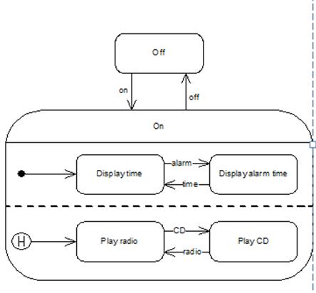
Concurrent states-
• Composite state can be decomposed into two or more orthogonal, concurrent state machine diagrams
– Concurrent state machines separated by dashed line indicating concurrent boundary
• The choices CD/Radio and Time/Alarm time are orthogonal
• History pseudostate indicates that CD/Radio state machine goes back to state clock was in when switched off
– History pseudostate points to state that is active when no history
22. Main elements of activity diagram: definitions, des, examples.
Activity diagrams are a technique to describe procedural logic, business process, and work flow. In many ways, they play a role similar to flowcharts, but the principal difference between them and flowchart notation is that they support parallel behavior.
• Initial node or start marker, activity final or stop marker (pseudostates). An action is something an object does, such as it sending a message
• Action caused by an event can be recorded on transition after a forward slash
• Guards- It may be the case that an event only causes a transition if certain conditions are satisfied
• Conditions can be specified in a guard (e.g.,
[last copy], [not last copy], [x <= 3], etc.)
• Guard expression can be any expression that has a boolean value (i.e., true or false)
• In a guard, can use normal language, object constraint language (OCL), programming language – anything that allows for an unambiguous condition to be specified
• Join merges two or more threads into one
• Fork splits one thread into two or more concurrent threads
Trigger-event
• Partitions (“swim lanes”)- Can use partitions or “swim lanes” to record the actions within the activity that are carried out by each
– Class
– Company department
– Actor
– User
• Can also partition actions according to which use cases they belong to
• Flows and edges- Flow or edge is arrow connecting actions in activity diagram
• Simplest flow simply carries token
• Can name flow if desired (but usually not necessary)
• If awkward to connect two actions, can use connectors
– Avoid connectors if possible!
• Can pass objects along flows

23. Decomposing an action on activity diagram: definition, description, example.
Activity diagrams are a technique to describe procedural logic, business process, and work flow. In many ways, they play a role similar to flowcharts, but the principal difference between them and flowchart notation is that they support parallel behavior.
Figure 1 shows a simple example of an activity diagram. We begin at the initial node action and then do the action Receive Order. Once that is done, we encounter a fork. A fork has one incoming flow and several outgoing concurrent flows.

24. Partitions, expansion regions, flow final, join specifications: definitions, description, examples
• Partitions (“swim lanes”)- Can use partitions or “swim lanes” to record the actions within the activity that are carried out by each
– Class
– Company department
– Actor
– User
– …
• Can also partition actions according to which use cases they belong to
Дата публикования: 2015-11-01; Прочитано: 3594 | Нарушение авторского права страницы | Мы поможем в написании вашей работы!
